Every EMC engineer eventually meets the same situation. A product fails radiated emissions testing, the spectrum looks chaotic, and the first explanation sounds logical but turns out to be wrong. Recently I worked on a product that showed significant broadband radiated emissions across almost the entire measured band. At first glance the spacing between peaks suggested a digital clock source. The initial data appeared to show something resembling a harmonic series. That assumption did not survive careful investigation.
The Failed Configuration
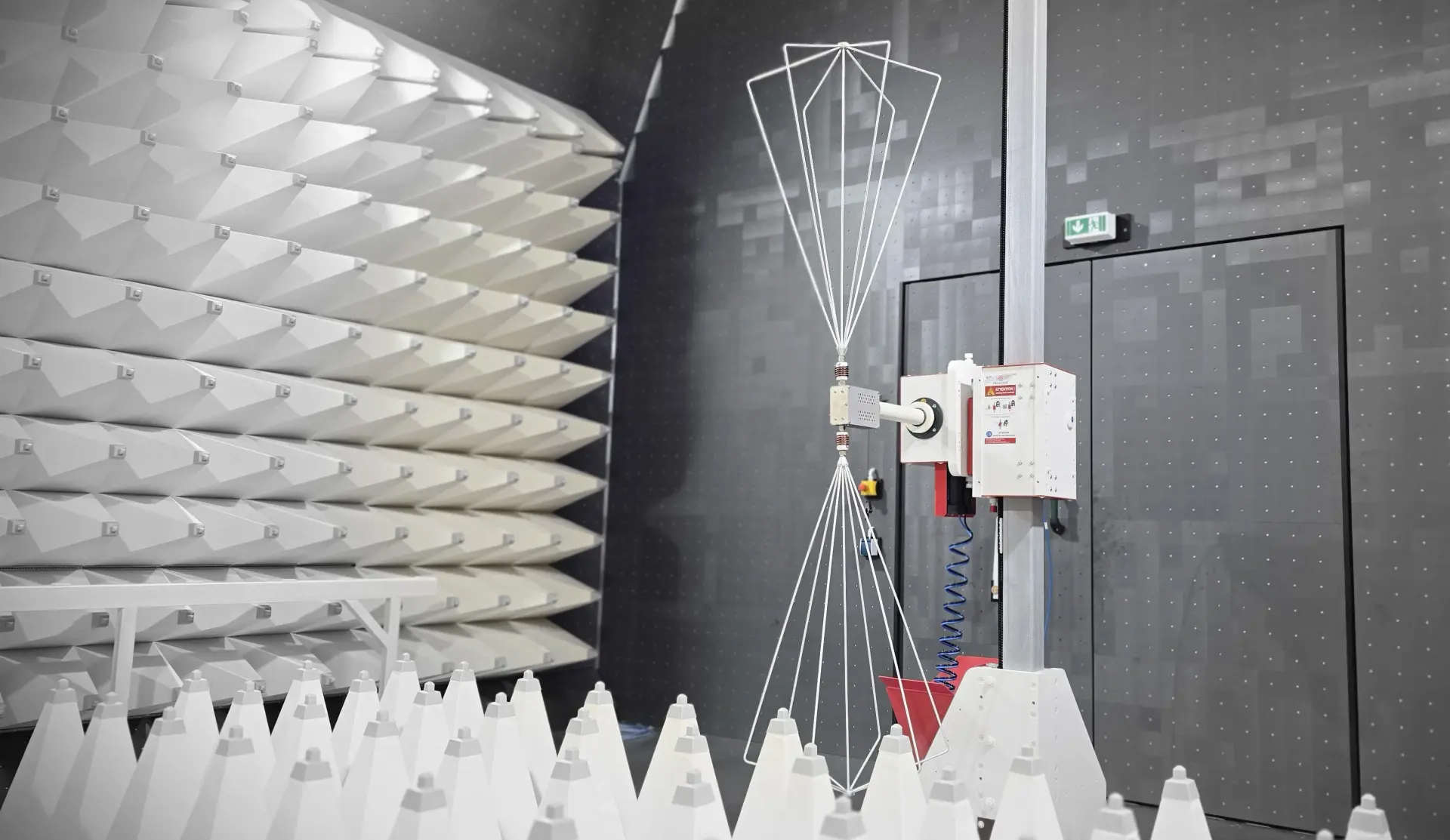
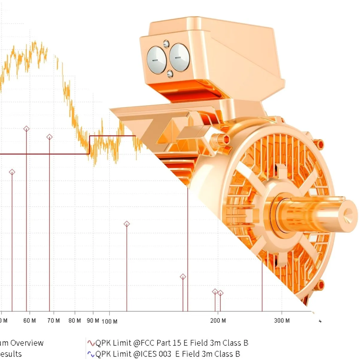
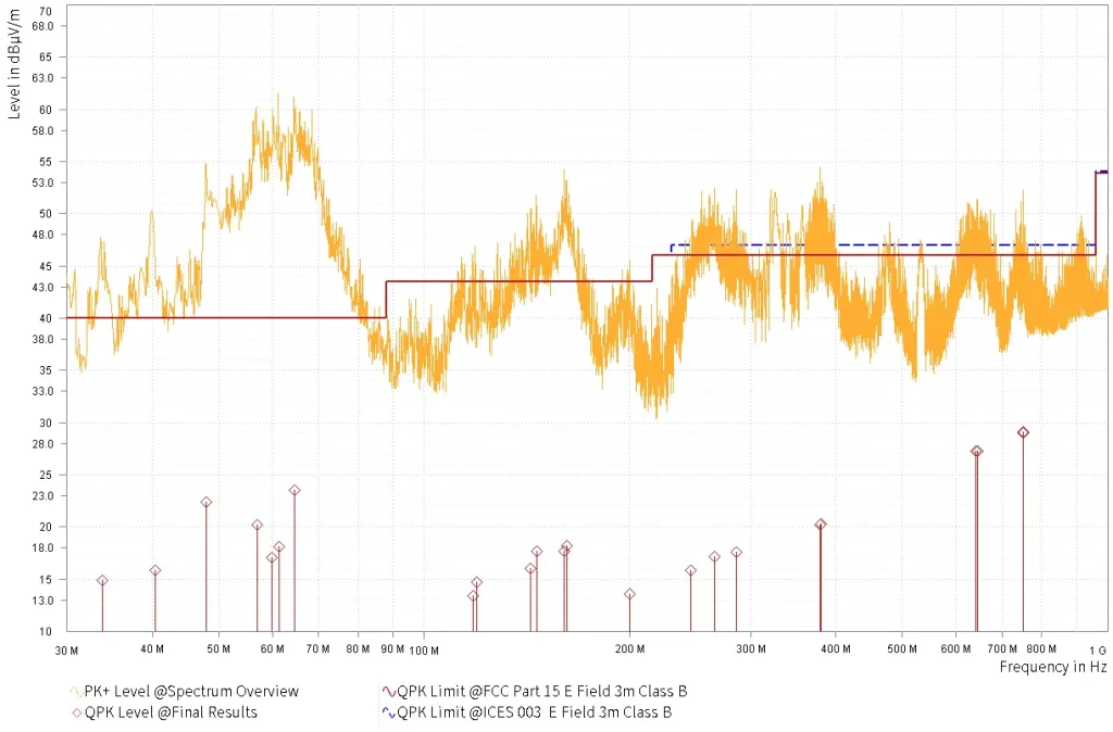
In its original form, the product included a brushed DC motor mounted inside the enclosure and connected directly to the controller. During 3 meter radiated emissions testing to Class B limits, the system failed. Below is the original scan.
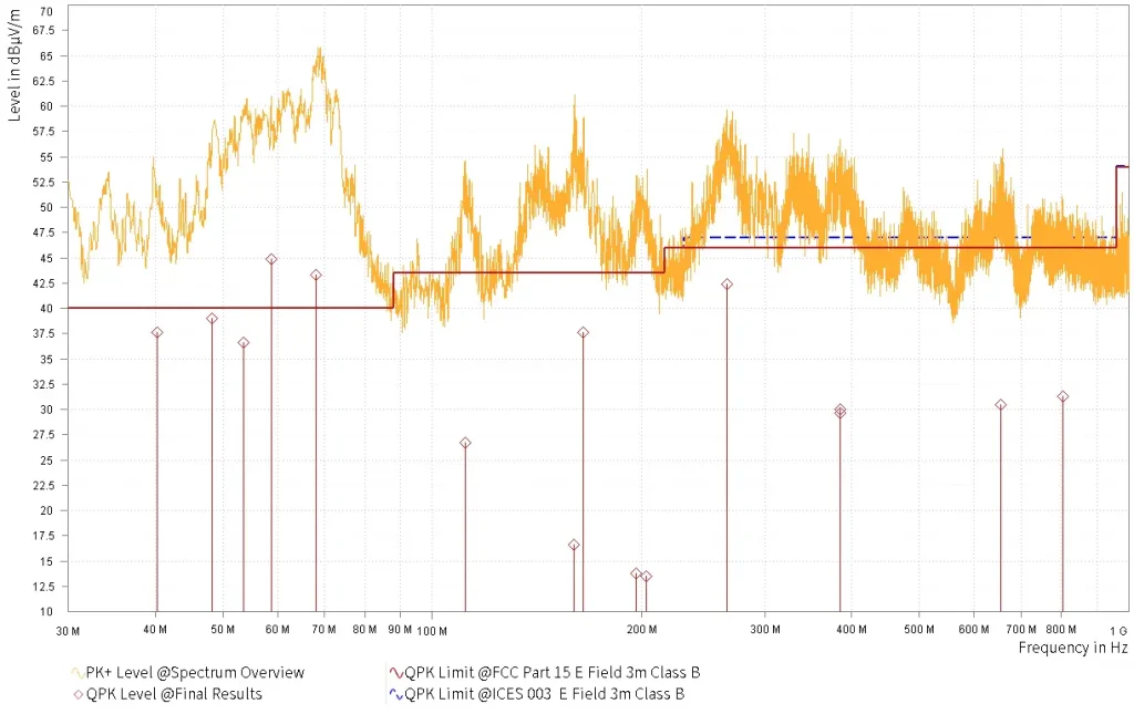
Looking at this plot carefully, several things stand out. Between roughly 50 MHz and 80 MHz the emission level rises sharply, peaking in the mid 60 dB microvolt per meter range. This is not a narrow harmonic spike. It is wideband energy.
From 150 MHz to 300 MHz there is a broad hump where the average noise floor remains elevated. This is a classic region where motor leads begin behaving like effective antennas. At these frequencies, even relatively short wiring can radiate efficiently when driven by fast transient currents.
The quasi peak results are scattered across the spectrum rather than forming a clean harmonic ladder. That is an important observation. True clock harmonics usually show consistent spacing and predictable decay. Here the energy is irregular and distributed, a strong indication of impulsive broadband noise.
The original trace also rides close to the regulatory limit over large portions of the band. That is not a robust design margin. Even small production tolerances could push additional units over the limit during radiated emissions testing.
Root Cause Investigation
On the bench, near field probing was performed around the PCB, switching regulators, and digital clock sources. None of these areas correlated strongly with the dominant emissions seen in the chamber.
Probing near the brushed DC motor told a different story. Brush commutation generates repetitive arcing events. Each arc produces very fast current transitions. Fast transitions contain high frequency spectral components that extend well into the hundreds of megahertz. The motor housing and connected leads provide a path for this energy to couple into free space.
What looked like a harmonic clock problem was in fact broadband brush noise. The earlier impression of evenly spaced peaks was most likely influenced by measurement method. When a single sweep captures intermittent impulsive events, the trace can appear to contain discrete peaks. Once multiple sweeps are accumulated and the trace is allowed to fully populate, the true broadband nature becomes visible.
Engineering Modifications
Several mitigation steps were evaluated. First, the motor was treated as the primary source. Where possible, suppression should be implemented at the origin of the noise. Motor suppression capacitors across the brushes reduce high frequency components before they travel onto the supply leads.
Second, attention was given to the motor supply wiring. Conducted noise travelling along those leads was converting into radiated energy. Proper filtering and impedance control at the cable interface is critical in this frequency region.
To confirm the diagnosis, the motor was temporarily placed outside the anechoic chamber. The connection to the internal controller was made through a properly mounted filter at the chamber boundary. With this configuration, the system passed radiated emissions testing.
This was a decisive result. It confirmed that the motor assembly and its coupling path were the dominant contributors, not the controller electronics.
The Improved Configuration
After implementing motor suppression and improved filtering, the product was retested. The results are shown below.
The difference is clear.
The elevated region between 50 MHz and 80 MHz is significantly reduced. The hump between 150 MHz and 300 MHz remains visible but at a lower amplitude. Most importantly, the quasi peak results now sit below the Class B limit with measurable margin during radiated emissions testing.
The overall broadband noise floor has decreased across the spectrum. This is not a marginal improvement. It is a structural reduction in emission energy.
What This Case Teaches
This case reinforces several practical lessons.
• Not every evenly spaced peak is caused by a digital clock.
• Single sweeps can mislead interpretation of impulsive noise.
• Brushed DC motors are naturally broadband emitters.
• Motor leads often become efficient radiators above 100 MHz.
• The most effective mitigation strategy is to control the noise at its source and manage the conducted path before it becomes radiated energy.
Most importantly, proper investigation requires slowing down and measuring methodically. EMC problems rarely disappear by adding random ferrites. They are solved by understanding where the energy originates and how it couples. In this case, once the motor was treated as the primary source and the coupling path was controlled, compliance followed naturally.
EMC is not magic. It is simply electromagnetic energy finding a path. When you understand the path, you control the outcome. For structured EMC testing support, careful investigation and controlled validation always produce better results than guesswork.
Related Articles